
Sub-Total: $0.00
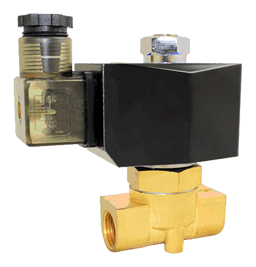
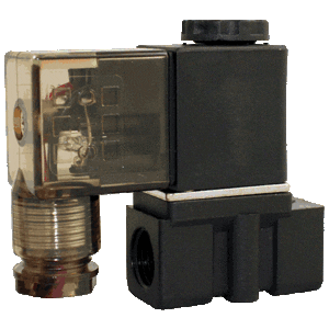
Solenoid Valve Specifications and Dimensions: 2WO040 Series
$105.94
Description
| Specifications | |||
| Model | 2WO040-3/8 | ||
| Port Size | 3/8″ NPT | ||
| Orifice | 4mm | ||
| Cv | 0.6 | ||
| Valve Type | 2-Way | ||
| Action | Direct Acting (Poppet)
Fast Response Time: <20msec |
||
| De-Energized State | Normally Open (NO) | ||
| Body Material |
|
||
| Seal Material |
|
||
| Operating Temperature |
|
||
| Operating Pressure | Vacuum to 60 PSI | ||
| Electrical Connection | DIN 43650A | ||
| Coil Power | 12W to 30W | ||
| Voltage Options |
|
||
| Voltage Tolerance | ±10% of Specified Voltage | ||
| Ingress Protection | IP65 | ||
| Insulation Class | H Class | ||
| Coil Duty | 100% ED, Continuous Duty | ||
| Installation | No Orientation Requirement | ||
| Service | Liquid, Water, Oil, Air, Gas, Steam (with Viton) | ||
| Dimensions | |||||||
|
|
|||||||

| Dimensions | |||||||||||||||||||||||||||||||||||
| 2W/O040 Series Solenoid Valve Dimensions | |||||||||||||||||||||||||||||||||||
| Model | Port | A | B | C | D | E | F | ||||||||||||||||||||||||||||
| 2WO040-3/8 | 1/4″ NPT | 96.0 | 90.6 | 54.0 | 50.0 | 31.8 | 19.7 | ||||||||||||||||||||||||||||
| Dimensions for Reference Use Only: Units in mm
2WO040 Series: 2/2 Direct Acting Normally Open Valve
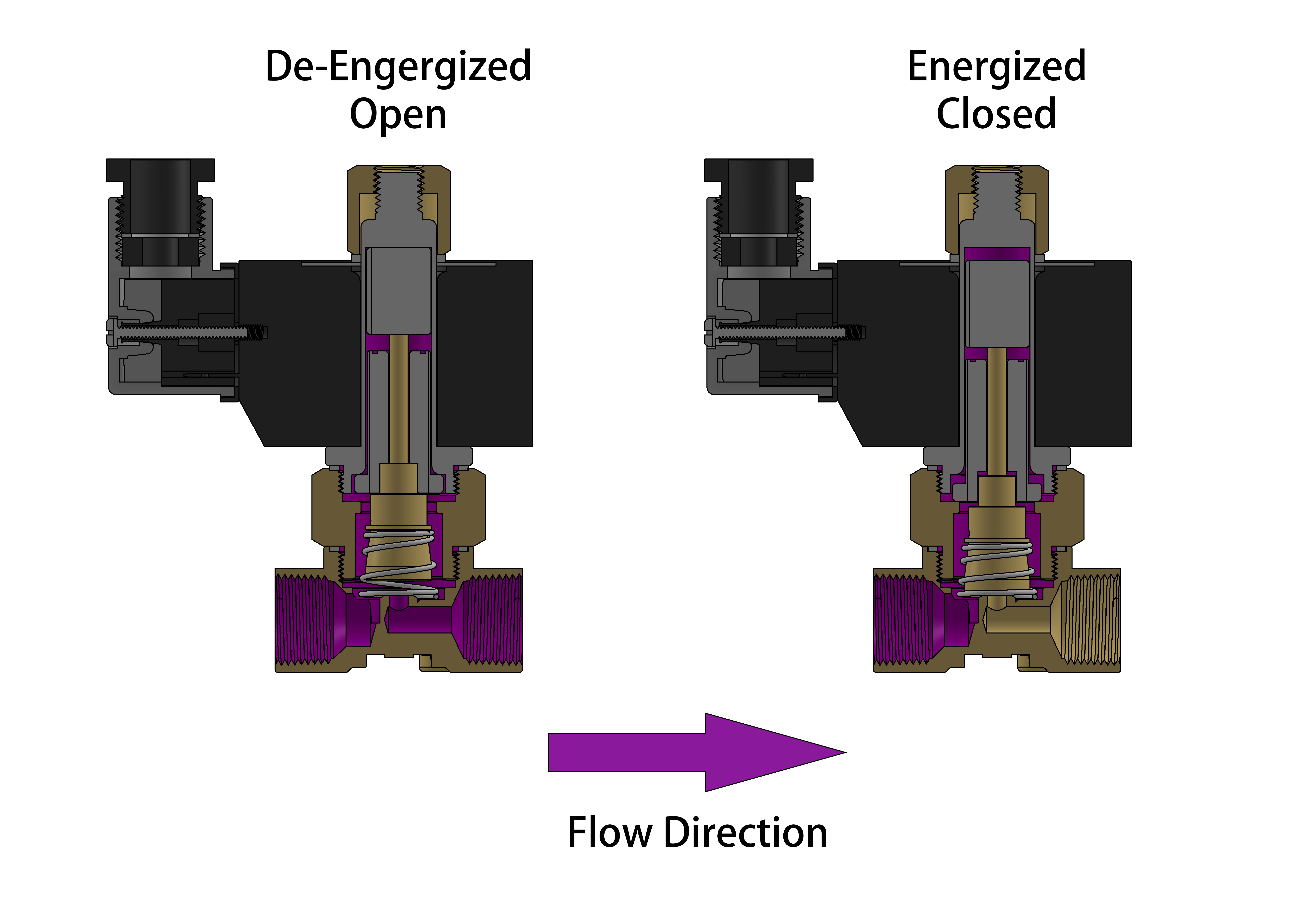
The 2WO040 series normally open solenoid valve is direct acting, it does not require a minimum operating differential pressure. As shown in the diagram below, when the coil is energized, it pushes the solenoid plunger downward to close the main valve orifice and closes the valve. When the coil is de-energized, the spring forces the plunger upward to open the valve main orifice and opens the valve. ALL standard valves are supplied with Continuous Duty Coils of the proper class of insulation for the service indicated on the valve. It is normal for the coil temperature may become hot after being energized for extended periods. Smoke or burning odor indicates excessive coil temperature and the power should be disconnected to the coil immediately.
SERVICE LIFE: The service life of the solenoid valve depends on the operating conditions such as pressure, temperature, type of medium, and the voltage. Normally the STC solenoid valves are reliable for more than 5 million cycles.
Electrical Coil Connections To Connect a DIN Coil:
To Connect a Grommet Coil:
|
|||||||||||||||||||||||||||||||||||
Related products
-

STC Solenoid Valve Manifold Dimensions (Units in mm)(4V-400M)
Price range: $9.01 through $410.30 Select options This product has multiple variants. The options may be chosen on the product page -
Solenoid Valve Specifications and Dimensions: 2P025 Series
$34.37 Select options This product has multiple variants. The options may be chosen on the product page -
Solenoid Valve Specifications and Dimensions: 2P025-S Series
$37.93 Select options This product has multiple variants. The options may be chosen on the product page -
STC Solenoid Valve Manifold Dimensions (Units in mm)(4V-300M)
Price range: $9.01 through $246.18 Select options This product has multiple variants. The options may be chosen on the product page
Reviews
There are no reviews yet.