
Sub-Total: $0.00
High Pressure Solenoid Valve Specifications and Dimensions: 2E100-250 Series
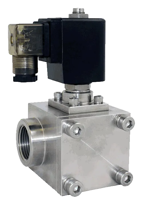
Price range: $718.05 through $1,189.89
- Port Size (NPT): 3/8″ NPT
1/2″ NPT
3/4″ NPT
1″ NPT
- Voltage:
- 1 = 12VDC
- 2 = 24VDC
- 2A = 24VAC
- 3 = 110VAC
- 4 = 220VAC
- ATEX = Explosion Proof Coil
- Electrical Connection:
- D = DIN
- Cv/Orifice:
- Cv = 4
Orifice = 10mm
- Cv = 9.2
Orifice = 15mm
- Cv = 16
Orifice = 20mm
- Cv = 24
Orifice = 25mm
- Cv = 4
- Services:
- Air, Liquid, Water, Steam
- Features:
- 2-Way, Normally Closed
Pilot Piston
Body: Stainless Steel
Seal: PTFE and FKM
Operating Temperature:
-40 to 356°F (-40 to 180°C)
Operating Pressure:
87 to 1450PSI at 72°F
Option: 87 to 2300PSI
Coil Power: 13 to 28W
Coil: Class H, IP65, CE
- 2-Way, Normally Closed
- Valve Symbol / Catalog:

Data Sheet:
Description
| Model | 2E100-3/8 | 2E150-1/2 | 2E200-3/4 | 2E250-1 |
|---|---|---|---|---|
| Port Size | 3/8″ NPT | 1/2″ NPT | 3/4″ NPT | 1″ NPT |
| Orifice | 10 mm | 15 mm | 20 mm | 25 mm |
| Cv | 4 | 9.2 | 16 | 24 |
| Valve Type | 2-Way, High Pressure | |||
| Action | Pilot Piston | |||
| De-Energized State | Normally Closed (NC) | |||
| Body Material | Valve Body: 304 Stainless Steel
Armature Assembly: Stainless Steel |
|||
| Seal Material | PTFE (Teflon) and Viton (FKM) | |||
| Operating Temperature | -40°F to 356°F (-40°C to 180°C) — With non-freezing medium | |||
| Operating Pressure | Standard: 87–1450 PSI @ 77°F
High Pressure (H) Option: 97–2300 PSI |
|||
| Electrical Connection | Standard: DIN 43650A
Upgrade: ATEX Explosion Proof Coil |
|||
| Coil Power | AC: 33VA
DC: 13–40W |
|||
| Voltage Options | 12VDC, 24VDC, 24VAC, 110/120VAC, 220/240VAC | |||
| Voltage Tolerance | ±10% | |||
| Ingress Protection | IP65 | |||
| Insulation Class | H Class | |||
| Coil Duty | 100% ED, Continuous Duty | |||
| Installation | No orientation requirement.
Optimum: Flow horizontal & solenoid vertical. Recommended: 150 mesh strainer, porosity ≤ 100µ. |
|||
| Service | Liquid, Water, Oil, Air.
Option: Cryogenic material with all PTFE seals & seat. |
|||
| 3D STEP | 2E100-3/8 | 2E150-1/2 | 2E200-3/4 | 2E250-1 |
| 3D PDF | 2E100-3/8 | 2E150-1/2 | 2E200-3/4 | 2E250-1 |
| 3D Solidworks | 2E100-3/8 | 2E150-1/2 | 2E200-3/4 | 2E250-1 |
| 2D AutoCAD | 2E100-3/8 | 2E150-1/2 | 2E200-3/4 | 2E250-1 |

| Model | Port | A | B | C | D | E |
|---|---|---|---|---|---|---|
| 2E100-3/8 | 3/8″ NPT | 124.8 | 55.7 | 60.2 | 105.8 | 57.2 |
| 2E150-1/2 | 1/2″ NPT | 136.6 | 65.0 | 70.0 | 111.6 | 57.2 |
| 2E200-3/4 | 3/4″ NPT | 140.7 | 74.2 | 80.0 | 113.7 | 57.2 |
| 2E250-1 | 1″ NPT | 150.7 | 88.4 | 90.0 | 118.7 | 57.2 |
Electrical Coil Connections
To Connect a DIN Coil:
- Remove the Philips screw from the plastic housing and unplug from the DIN coil.
- Use the removed screw to push the terminal block out of the plastic DIN housing.
- Note the “1”, “2”, and ground “⏚” symbols.
- For DC DIN Coils, connect “1” to your positive lead and “2” to your negative lead.
- For AC DIN Coils, connect “1” to your HOT lead, “2” to your NEUTRAL lead, and “⏚” to your ground lead, if required.
To Connect a Grommet Coil:
- For DC Coils, connect the red wire to your positive lead and the black wire to your negative lead.
- For AC Coils, connect the black wire to your HOT lead and the white wire to your NEUTRAL lead.
- For Coils provided with Molded Cables, the color of the wire indicates the type of lead:
- GREEN = Ground Wire
- BLUE = Positive or HOT Wire
- BROWN = Negative or Neutral Wire

Additional information
| Size | 2E100-3/8, 2E150-1/2, 2E200-3/4, 2E250-1 |
|---|
Related products
-

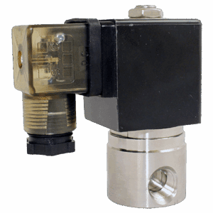
Solenoid Valve Specifications and Dimensions: 2S025-050 Series
Price range: $57.22 through $79.41 Select options This product has multiple variants. The options may be chosen on the product page -
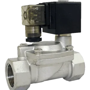
Slow Closing, Anti Water Hammer Solenoid Valve Specifications and Dimensions: 2D150-500-2DS150-500 Series
Price range: $153.12 through $635.08 Select options This product has multiple variants. The options may be chosen on the product page -
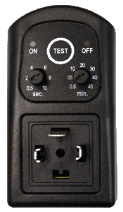
2W200C-T Timer
$46.62 Add to cart -
STC Programmable Digital Timer: Models 2W200C-T-D Installation Procedure
$76.47 Add to cart
Reviews
There are no reviews yet.