
Sub-Total: $0.00
Solenoid Coils 2WO250C

$66.69
Voltage:
1 = 12VDC
2 = 24VDC
2A = 24VAC (50/60Hz)
3 = 110VAC (50/60Hz)
4 = 220VAC (50/60Hz)
Electrical Connection:
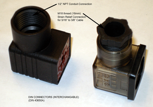
D = DIN (with conduit connector)
Power Rating:
25-30W
Applications:
For 2LS120-200, 2MS/2MSO120-500, 2P/2PO160-260, 2S/2W350-500, 2SO/2WO160-260 Series Solenoid Valves with DIN and 5/16″ Strain Relief Connection
Specifications:
Insulation: H Class, IP65
Duty Cycle: 100% ED
DIN 43650A
Description
Specifications
| Model | 100C | 200C | 2W200C | 2WO250C | 2W350C |
| Coil Insulation & Protection Class | F Class, IP 65 | F Class, IP 65 | H Class, IP 65 | H Class, IP 65 | H Class, IP 65 |
| Coil Duty Cycle | 100%ED | 100%ED | 100%ED | 100%ED | 100%ED |
| DIN Electrical Connection | DIN 43650C (with LED Indicator)
Strain Relief Connection use 6mm to 1/4″ cable Option: 1/2″ Female NP |
DIN 43650B (PG 9) (with LED Indicator)
Strain Relief Connection use 6mm to 1/4″ cable PG 9 (Standard) Option: 1/2″ Female NPT Conduit Connection |
DIN 43650A (with LED Indicator)
Strain Relief Connection use 6mm to 8mm – 5/16″ cable PG 11 (Standard) Option: 1/2″ Female NPT Conduit Connection |
DIN 43650A (PG 11) (with LED Indicator)
Strain Relief Connection use 6mm to 8mm – 5/16″ cable PG 11 (Standard) Option: 1/2″ Female NPT Conduit Connection |
DIN 43650A (PG 11) (with LED Indicator)
Strain Relief Connection use 6mm to 8mm – 5/16″ cable PG 11 (Standard) Option: 1/2″ Female NPT Conduit Connection |
| Grommet Electrical Connection | G = Grommet (12″ Lead Wire) | G = Grommet (12″ Lead Wire) | N/A | N/A | N/A |
| Power Consumption | 2.5 Watt (Holding), Inrush 160% for AC Power Supply | 3 to 6.5 Watt (Holding), Inrush 160% for AC Power Supply | 12 to 20 Watt (Holding), Inrush 160% for AC Power Supply | 25 to 40 Watt (Holding), Inrush 160% for AC Power Supply | 25 to 40 Watt (Holding), Inrush 160% for AC Power Supply |
| Ambient Temperature | -30°C to 70°C | -30°C to 70°C | -20°C to 50°C | -20°C to 50°C | -20°C to 50°C |
| Certification | CE Certification | CE Certification
Options: UL, CSA; FM (Explosion Proof) |
CE Certification
Options: ATEX (Explosion Proof) |
CE Certification | CE Certification |
Dimensions (Units in mm)
A. 100C (DIN 43650C)
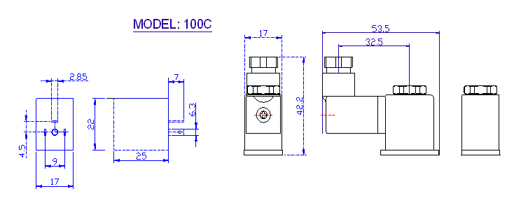
B. 200C (DIN 43650B PG9)


C. 100C (DIN 43650C)

D. 100C (DIN 43650C)

Electrical Connection Procedure:
CAUTION: Do no energize the solenoid coil when it is not installed onto the valve. It may cause it to overheat and create a fire hazard.
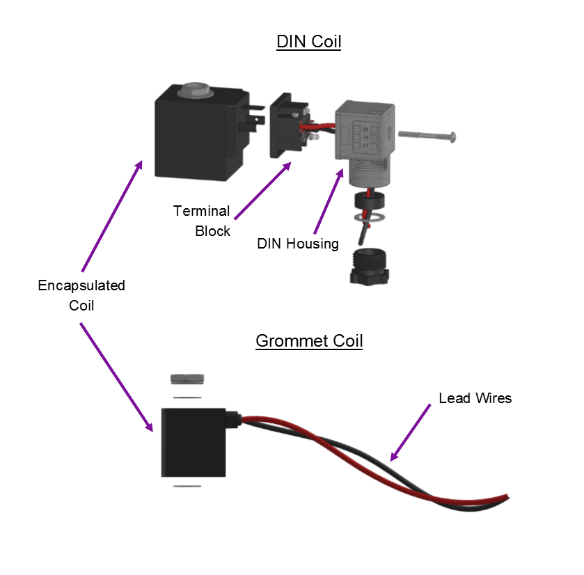
To Connect a DIN Coil:
-
- Remove the Philips screw from the plastic housting & unplug from the DIN coil.
- Use the removed screw to push the terminal block out of the plastic DIN housing.
- Note the “1”, “2”, and ground “⏚” symbols.
- For DC DIN Coils, connect “1” to your positive lead and “2” to your negative lead.
- For AC DIN Coils, connect “1” to your HOT lead, “2” to your NEUTRAL lead, and “⏚” to your ground lead, if required.
To Connect a Grommet Coil:
-
- For DC Coils, connect the red wire to your positive lead and the black wire to your negative lead.
- For AC Coils, connect the black wire to your HOT lead and the white wire to your NEUTRAL lead.
- For Coils provided with Molded Cables, the color of the wire indicates the type of lead:
- GREEN = Ground Wire
- BLUE = Positive or HOT Wire
- BROWN = Negative or Neutral Wire
Connection Options: Conduit and Strain Relief Connections:
Related products
-

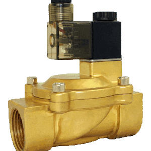
Normally Open Solenoid Valve Specifications & Dimensions: 2SO030-040 Series
Price range: $106.23 through $119.00 Select options This product has multiple variants. The options may be chosen on the product page -
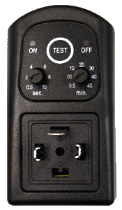
2W200C-T Timer
$46.62 Add to cart -
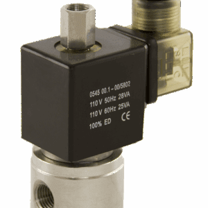
Solenoid Valve Specifications and Dimensions: 3S020-035 Series
$110.05 Select options This product has multiple variants. The options may be chosen on the product page -
Solenoid Valve Specifications and Dimensions: 2V130-250 Series
Price range: $109.68 through $211.49 Select options This product has multiple variants. The options may be chosen on the product page
Reviews
There are no reviews yet.