
Sub-Total: $0.00
Solenoid Valve Specifications and Dimensions: 2W025-050 Series
$104.91
Description
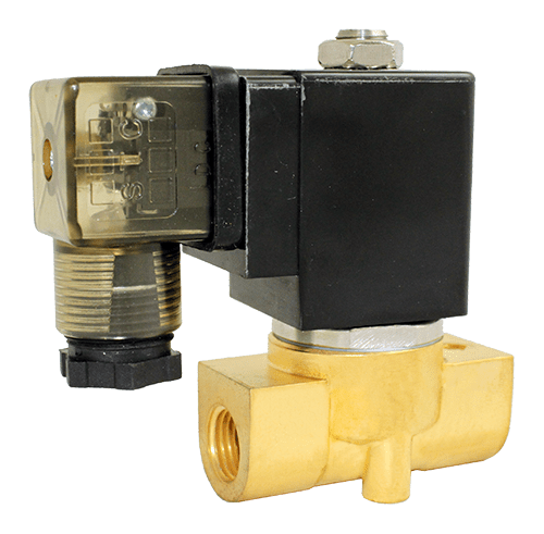
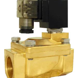
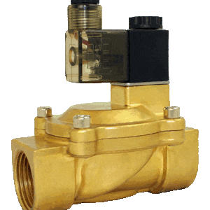
The 2P025 is a direct-acting, normally closed solenoid valve with a two-way operation & two ports.
Specifications
| Model | 2H012-1/8 | 2H016-1/4 | ||
| Port Size | 1/8″ NPT | 1/4″ NPT | ||
| Orifice | 1.2mm | 1.6 | ||
| Cv | 0.05 | 0.09 | ||
| Valve Type | 2-Way, 2-Position, Body Ported | |||
| Action | Direct Acting (Poppet)
Fast Response Time: <20msec |
|||
| De-Energized State | Normally Closed (NC) | |||
| Body Material |
|
|||
| Seal Material |
|
|||
| Operating Temperature |
|
|||
| Operating Pressure | 0 PSI to 1000 PSI | |||
| Electrical Connection |
|
|||
| Coil Power |
|
|||
| Voltage Options |
|
|||
| Voltage Tolerance | ±10% of Specified Voltage | |||
| Ingress Protection | IP65 | |||
| Insulation Class | F Class | |||
| Coil Duty | 100% ED, Continuous Duty | |||
| Installation | No Orientation Requirement | |||
| Service | Liquid, Water, Oil, Air, Gas, Cryogen | |||
Dimensions
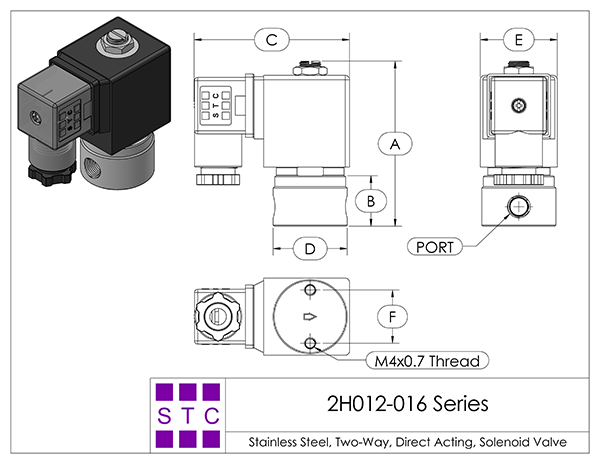
2S012-020-A Series Solenoid Valve Dimensions
|
||||||||||||||||||||||||||||||||||||
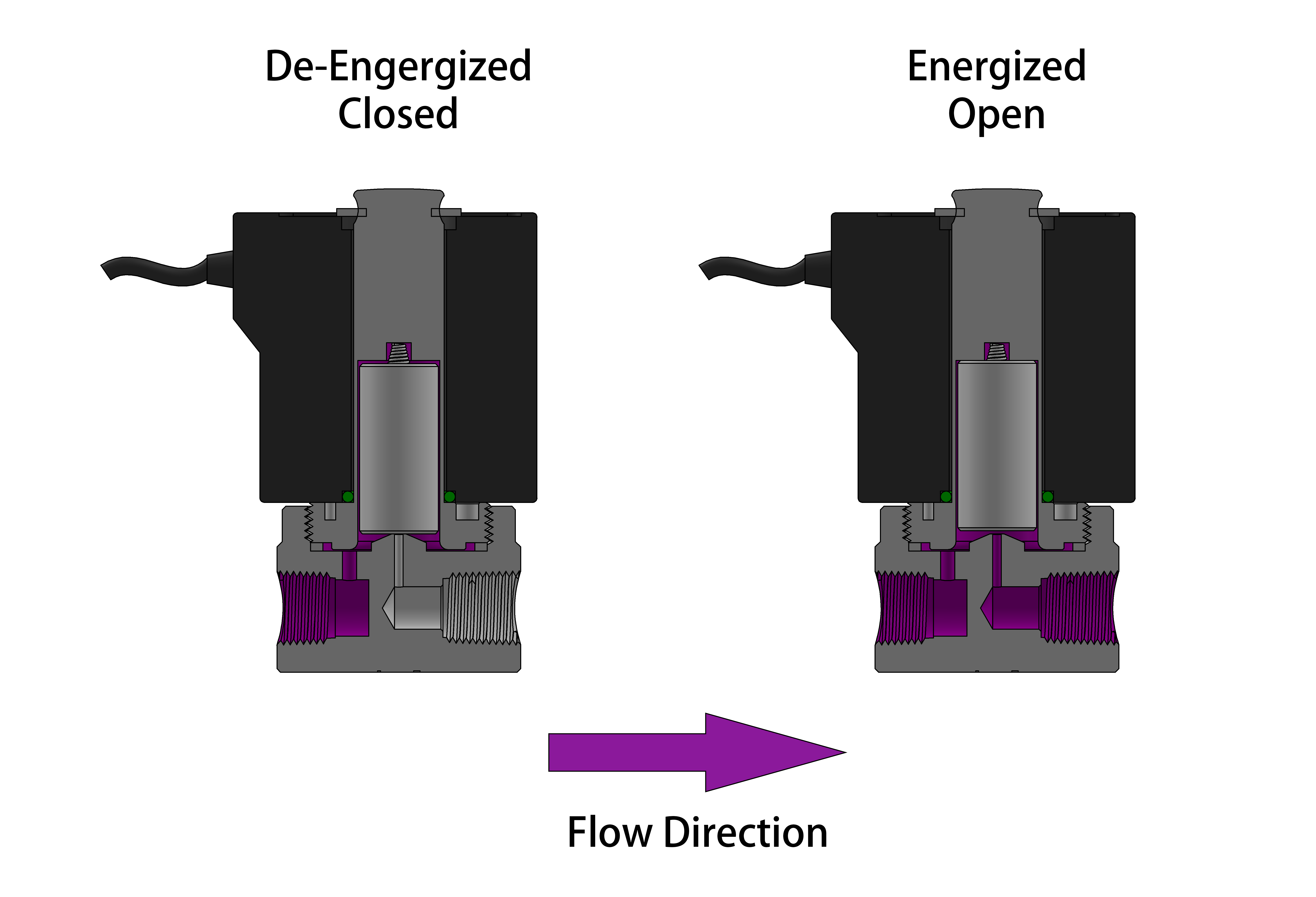
The 2H012-016 valves are direct acting solenoid valves that do not require a minimum operating differential pressure. As shown in the diagram below, when the coil is de-energized (left diagram), the plunger rests on the main orifice and is held in place by the plunger spring force, sealing the valve. When the coil is energized (right diagram), the solenoid lifts the plunger and allows the working medium to flow through the orifice. The working medium and flow direction are indicated in purple in the diagram.
STC’s high performance direct acting plastic body solenoid valves offer reliability, compact and rugged designs, low power consumption, high-speed response, long-life cycle (over 10 million cycles), DIN connections and indicator lights, pre-wired electrical connections, manifold mounting options, and simple installation, maintenance, and control.
Operation Diagram
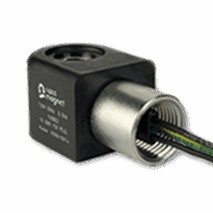
Electrical Coil ConnectionsTo Connect a DIN Coil:
- Remove the Philips screw from the plastic housting & unplug from the DIN coil.
- Use the removed screw to push the terminal block out of the plastic DIN housing.
- Note the “1”, “2”, and ground “⏚” symbols.
-
-
-
- For DC DIN Coils, connect “1” to your positive lead and “2” to your negative lead.
- For AC DIN Coils, connect “1” to your HOT lead, “2” to your NEUTRAL lead, and “⏚” to your ground lead, if required.
-
-
To Connect a Grommet Coil:
- For DC Coils, connect the red wire to your positive lead and the black wire to your negative lead.
- For AC Coils, connect the black wire to your HOT lead and the white wire to your NEUTRAL lead.
- For Coils provided with Molded Cables, the color of the wire indicates the type of lead:
-
-
- GREEN = Ground Wire
- BLUE = Positive or HOT Wire
- BROWN = Negative or Neutral Wire
-
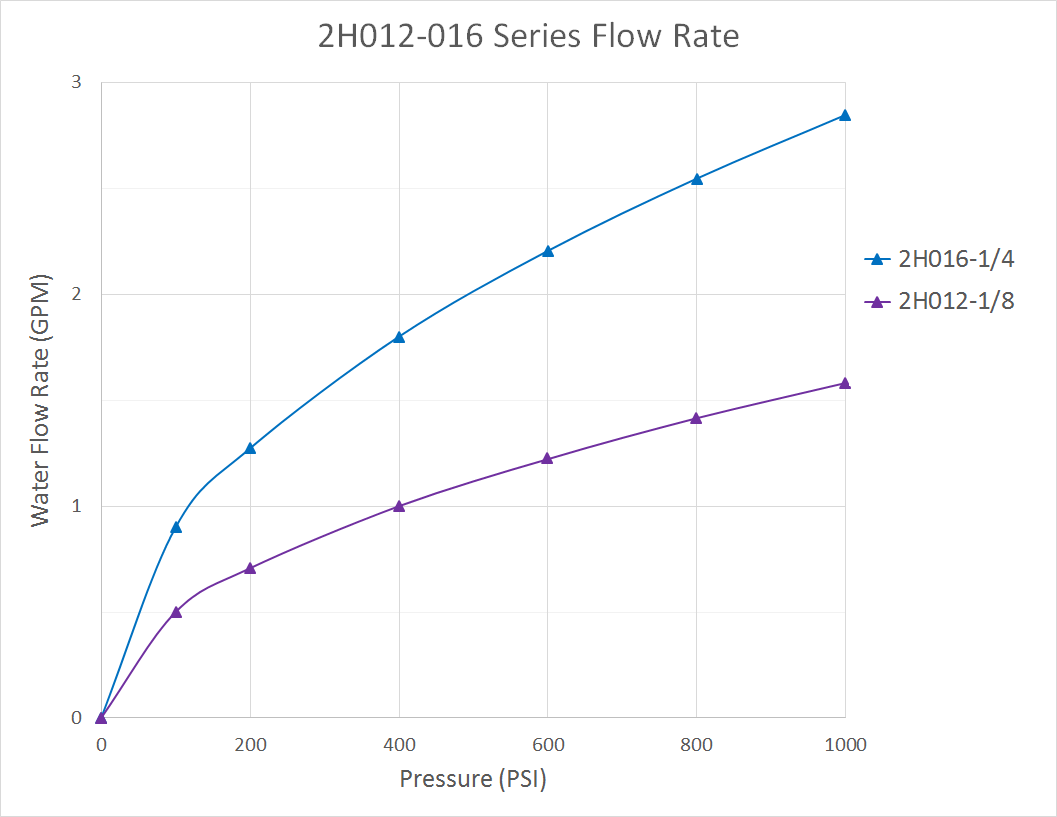
| Flow Rate | ||||||
 |
Additional information
| Part No. | 2H012-1/8, 2H016-1/4 |
|---|
Related products
-

Solenoid Valve Specifications and Dimensions: 2R130-500 and 2RS130-500 Series
Price range: $116.45 through $561.58 Select options This product has multiple variants. The options may be chosen on the product page -
Solenoid Coils 2WO250C
$66.69 Add to cart -
Solenoid Valve Specifications and Dimensions: 2V130-250 Series
Price range: $109.68 through $211.49 Select options This product has multiple variants. The options may be chosen on the product page -
Explosion Proof Process Valves for Hazardous Locations 200C
$160.01 Add to cart

Reviews
There are no reviews yet.