
Sub-Total: $0.00
Solenoid Valve Specifications & Dimensions: 2P050
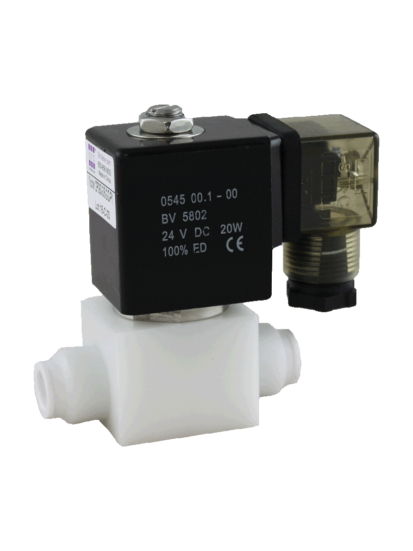
$213.14
Port Size (NPT):
1/4″ Female NPT
3/8″ Female NPT
3/8″ Push-In Fitting (pictured)
3/8″ OD Tube
Voltage (Explosion Proof):
2-ATEX = 24VDC
2A-ATEX = 24VAC
3-ATEX = 110VAC
4-ATEX = 220VAC
Electrical Connection:
2W00C ATEX Explosion Proof Coil
Cv/Orifice:
Orifice = 5mm
Services:
Air, Water, Liquid
Features:
2 Way Direct Acting
Normally Closed
Operating Pressure: Vacuum to 50PSI
Delrin Plastic Body (can be customized to any type of plastic)
Wetted Surfaces: Delrin, Stainless Steel, NBR, Viton O-Ring
Coil Power: 20W
Valve Symbol/Catalog:

Downloads:2P050.PDF
Description
| Part No. | Valve Pictures | Port Size | Voltage | Electrical Connection | Port No / Position / Solenoid | Power Consumption | Valve Symbol |
| 2P050-3/8 | 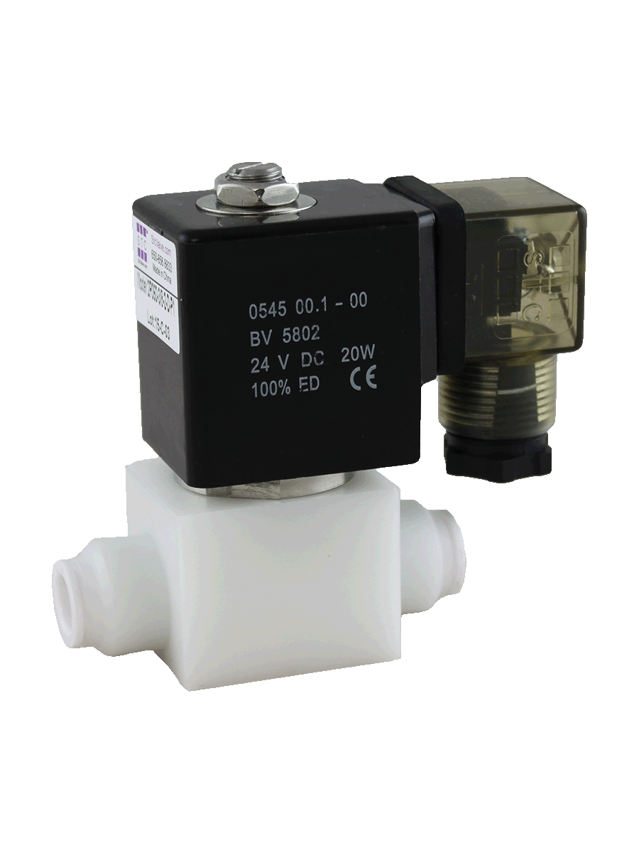 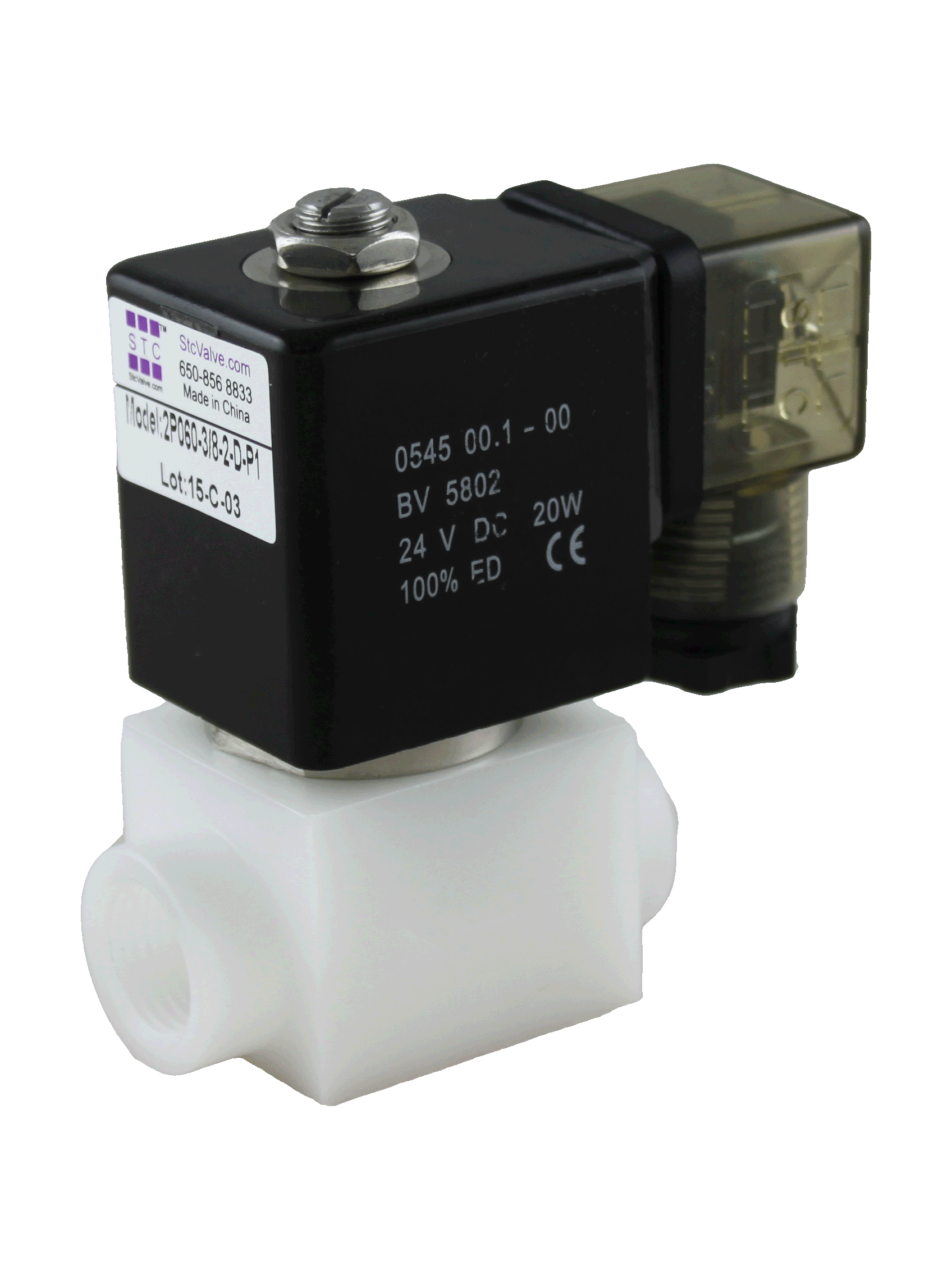 |
3/8″ Female NPT | 1 = 12VDC
2 = 24VDC2A = 24VAC 3 = 110VAC 4 = 220VAC (50/60Hz) |
G = Grommet
D = DIN (with LED Indicator) |
2/2/1
Direct Acting Normally Closed Two Way Valve |
3 to 6.5W |  |
| 2P050-3/8F | 3/8″ Push-In Fitting | ||||||
| 2P050-3/8T | 3/8″ OD Tube |
| Specifications | |
| Valve Type | 2 Way, Normally Closed (NC) |
| Action | Direct Acting |
| Orifice | 5.0mm |
| Operating Pressure | Vacuum to 50PSI |
| Port Size (Tube OD) | Options: 3/8″ OD Tube
3/8″ Push-In Fitting 3/8″ Female NPT |
| Wetted Surfaces | Valve Body: Delrin Plastic (can be customized to any type of plastic)
Seals: NBR (Buna N), Silicone, Viton Double Seals (Fitting Connection Only) Armature Assembly: Stainless Steel |
| Coil Duty | H Class, IP65, 100% ED Continuous Duty |
| Voltage | Options: 12, 24 VDC; 24, 110/120 (50/60Hz), 220/240 VAC (50/60Hz) |
| Voltage Tolerance | +/-10% of Specified Voltage |
| Coil Power | 20W |
| Electrical Connections | DIN43650A, Option: Molded Cable, ATEX Explosion Proof |
| Installation | No Orientation (Optimum Position: Flow Horizontal & Solenoid Vertical) |
| Service | Air, Water, Liquid |
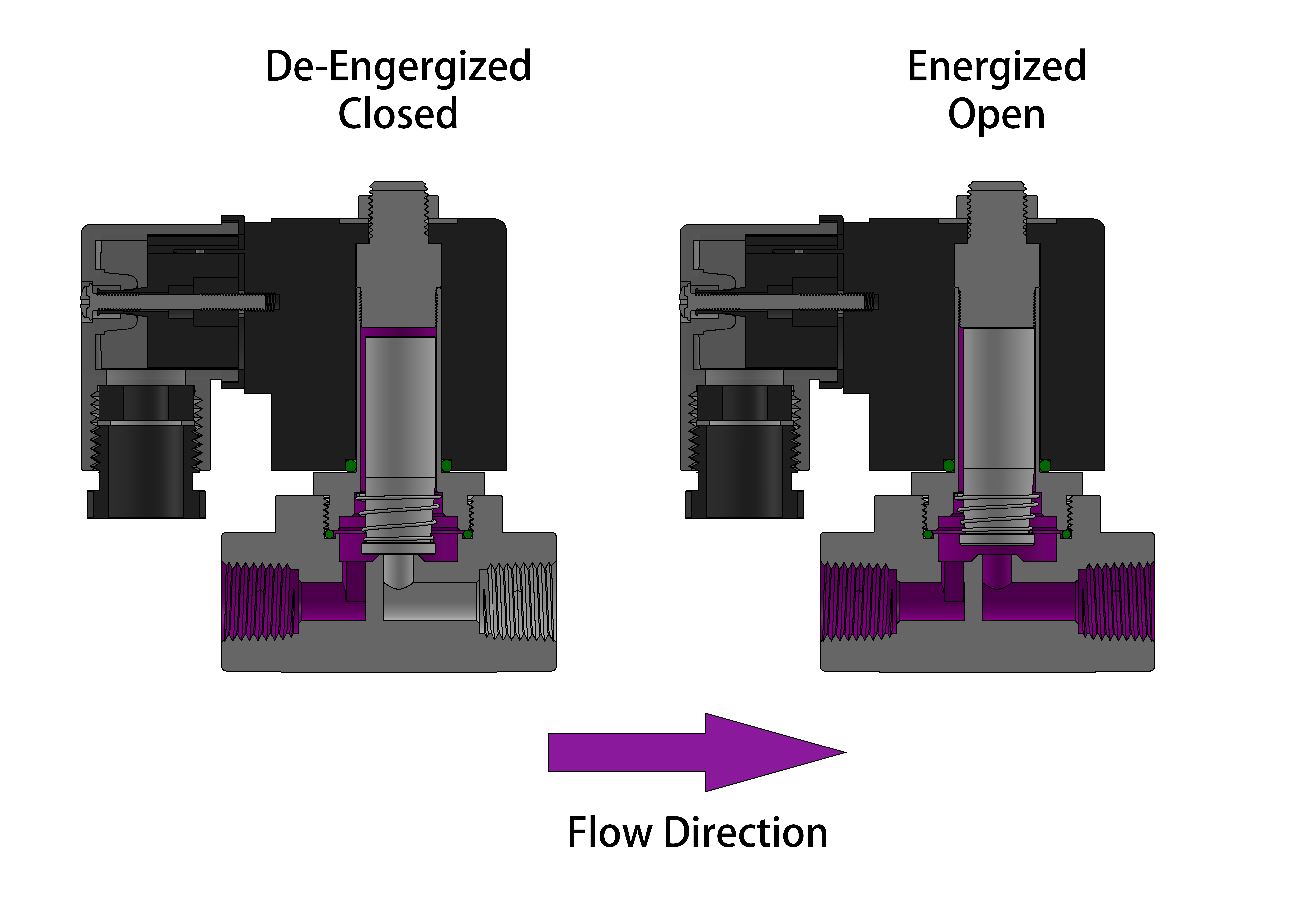
The 2P050 valve is a two-way, normally closed, direct acting valve and does not require a minimum differential pressure to operate. As shown in the diagrams below, when the coil is de-energized (left diagram), the plunger rests on the main orifice and is held in place by the plunger spring force, sealing the valve. When the coil is energized (right diagram), the solenoid lifts the plunger and allows the working medium to flow through the orifice. The working medium and flow direction are indicated in purple in the diagrams.
Benefits:
- Can be used in food grade, sanitary, and chemical applications.
- The valve body can be customized to any type of plastic to meet specific operating conditions.
Features
- Double Viton O-ring for improved sealing at the tube inlet and outlet.
- The threaded armature top screws into the armature tube, and then the connection is welded together. The threaded connection combined with welding allows for a longer lifespan of the valve.
- The armature tube is machined from a solid stainless steel bar – with no additional joints or connections, it can withstand higher pressure and more lifecycles.
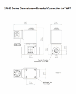
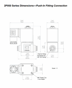
Electrical Coil Connections
-
- To Connect a DIN Coil:
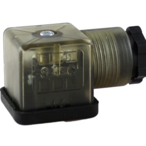
- Remove the Philips screw from the plastic housting & unplug from the DIN coil.
- Use the removed screw to push the terminal block out of the plastic DIN housing.
- Note the “1”, “2”, and ground “⏚” symbols.
- For DC DIN Coils, connect “1” to your positive lead and “2” to your negative lead.
- For AC DIN Coils, connect “1” to your HOT lead, “2” to your NEUTRAL lead, and “⏚” to your ground lead, if required.
- To Connect a DIN Coil:
- To Connect a Grommet Coil:
- For DC Coils, connect the red wire to your positive lead and the black wire to your negative lead.
- For AC Coils, connect the black wire to your HOT lead and the white wire to your NEUTRAL lead.
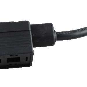
- For Coils provided with Molded Cables, the color of the wire indicates the type of lead:
- GREEN = Ground Wire
- BLUE = Positive or HOT Wire
- BROWN = Negative or Neutral Wire
Additional information
| Part No. | 2P050-1/4, 2P050-3/8, 2P050-3/8F, 2P050-3/8T |
|---|

Reviews
There are no reviews yet.