
Sub-Total: $0.00
Solenoid Valve Specifications and Dimensions: 2S012-020-A Series
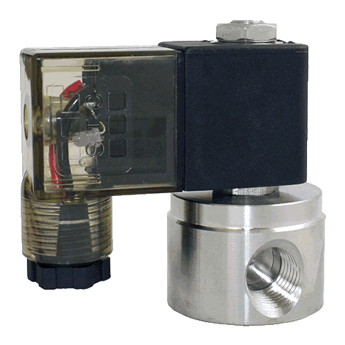
$52.94
Port Size (NPT)
1/8″ NPT
1/4″ NPT
1/8″ NPT
1/4″ NPT
Voltage
1 = 12VDC
2 = 24VDC
2A = 24VAC
3 = 110VAC
4 = 220VAC
E or ATEX = Explosion Proof Coil
Electrical Connection
G = Grommet
D = DIN (with LED)
Cv/Orifice
Cv = 0.05
Orifice = 1.2mm
Cv = 0.15
Orifice = 2.0mm
Services
Air, Liquid, Oil, Water
Features
2-Way, Normally Closed
Direct Acting
Body: Stainless Steel
Seal: NBR
Operating Temperature:
14 to 176°F
Operating Pressure:
0 to 200PSI
Coil Power: 3 to 6.5W
Response Time: <20msec Two Way NC Pneumatic Diagram
Data Sheet:
2S012-020-A.PDF
2S012-1/4A $47.69 1/4″ NPT
2S020-1/8A $47.69 1/8″ NPT Cv = 0.15
Orifice = 2.0mm 2-Way, Normally Closed
Direct Acting
Body: Stainless Steel
Seal: NBR
Operating Temperature:
14 to 176°F
Operating Pressure:
0 to 150PSI
Coil Power: 3 to 6.5W
Response Time: <20msec
Valve Symbol/Catalog

Data Sheet:
Description
| Specifications | |||||||
| Model | 2S012-1/8A | 2S012-1/4A | 2S020-1/8A | 2S020-1/4A | |||
| Port Size | 1/8″ NPT | 1/4″ NPT | 1/8″ NPT | 1/4″ NPT | |||
| Orifice | 1.2mm | 2.0mm | |||||
| Cv | 0.05 | 0.15 | |||||
| Valve Type | 2-Way | ||||||
| Action | Direct Acting (Poppet)
Fast Response Time: <20msec |
||||||
| De-Energized State | Normally Closed (NC) | ||||||
| Body Material |
|
||||||
| Seal Material |
|
||||||
| Operating Temperature |
|
||||||
| Operating Pressure | Vacuum to 200 PSI | Vacuum to 150 PSI | |||||
| Electrical Connection |
|
||||||
| Coil Power | 3W to 6.5W | ||||||
| Voltage Options |
|
||||||
| Voltage Tolerance | ±10% of Specified Voltage | ||||||
| Ingress Protection | IP65 | ||||||
| Insulation Class | H Class | ||||||
| Coil Duty | 100% ED, Continuous Duty | ||||||
| Installation | No Orientation Requirement
Optimum Position: Flow Horizontal and Solenoid Vertical |
||||||
| Service | Liquid, Water, Oil, Air | ||||||
Dimensions

| 2S012-020-A Series Solenoid Valve Dimensions | ||||||
| Model | Port | A | B | C | D | E |
| 2S012-1/8A | 1/8″ NPT | 62.7 | 66.6 | 31.5 | 20 | 48.7 |
| 2S012-1/4A | 1/4″ NPT | 62.7 | 66.6 | 34.5 | 25 | 48.7 |
| 2S020-1/8A | 1/8″ NPT | 62.7 | 66.6 | 31.5 | 20 | 48.7 |
| 2S020-1/4A | 1/4″ NPT | 62.7 | 66.6 | 34.5 | 25 | 48.7 |
| Dimensions for Reference Use Only: Units in mm | ||||||
To Connect the Valve Inlet & Outlet:
Connect the inlet & outlet to the valve ports according to the flow direction arrow marked on the valve
To Install the Coil:
Put the coils on to the armature tube of the valve. Place the lock washer & nut on to the armature tube. Hand tighten the nut, then use a wrench to tighten the nut another quarter-turn. Do not over-tighten the nut, as it may cause the armature tube to fail prematurely.
To Connect a DIN Coil:
1. Remove the Philips-head screw from the plastic DIN housing & unplug it from the DIN coil
2. From the screw opening, push the terminal block out from the plastic DIN housing.
3. Note the “1”, “2”, and ground “⏚” symbols on the underside of the DIN enclosure.
4. For DC DIN Coils, connect “1” to your Positive Lead & “2” to your Negative lead.
5. For AC DIN Coils, connect “1” to your HOT lead, “2” to your Neutral lead, & “⏚” to your ground if required.
Do not energize the coil without installing it onto the valve or connect the coil to a different voltage than specified. This will burn the coil and could create fire hazards.
Safety Note: Standard valves are supplied with continuous duty coils. The proper class of insulation for the service is indicated on the coil body. The coil temperature may rise significantly if energized for extended periods—this is normal. Although the coil is made of flame-retardant material, misuse of the coil could create fire hazards & generate smoke and/or a burning odor. If these conditions are encountered, the coil temperature has risen above safe levels and the power should be disconnected immediately.
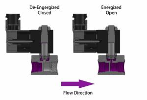
Operation: This valve is a two-way, normally closed, direct-acting valve & does not require a minimum differential pressure to operate. As shown in the diagrams below, when the coil is de-energized (left diagram), the plunger rests on the main orifice & is held in place by the plunger spring force, sealing the valve. When the coil is energized (right diagram), the solenoid lifts the plunger & allows the working medium to flow through the orifice. The working medium & flow direction are indicated in purple in the diagrams.
Operation Diagram
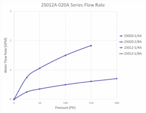
Flow Rate
Additional information
| Part No. | 2S012-1/8A, 2S012-1/4A, 2S020-1/8A, 2S020-1/4A |
|---|
Related products
-

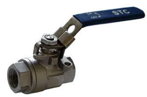
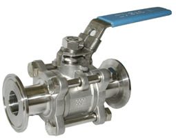
Stainless Steel Full Port Ball Valves(V2)
Price range: $34.27 through $196.83 Select options This product has multiple variants. The options may be chosen on the product page -
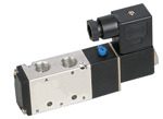
4-Way, 5-Port, 2-Position Directional, Pneumatic Solenoid Valves: 4V310-1/4 or -3/8
$60.93 Select options This product has multiple variants. The options may be chosen on the product page -
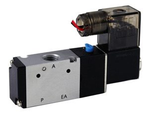
3-Way, 2-Position (3/2) Pneumatic Solenoid Valve: 3V110-1/8
Price range: $45.24 through $106.17 Select options This product has multiple variants. The options may be chosen on the product page -
Stainless Steel Full Port Ball Valves(V3C)
Price range: $153.47 through $1,880.23 Select options This product has multiple variants. The options may be chosen on the product page
Reviews
There are no reviews yet.